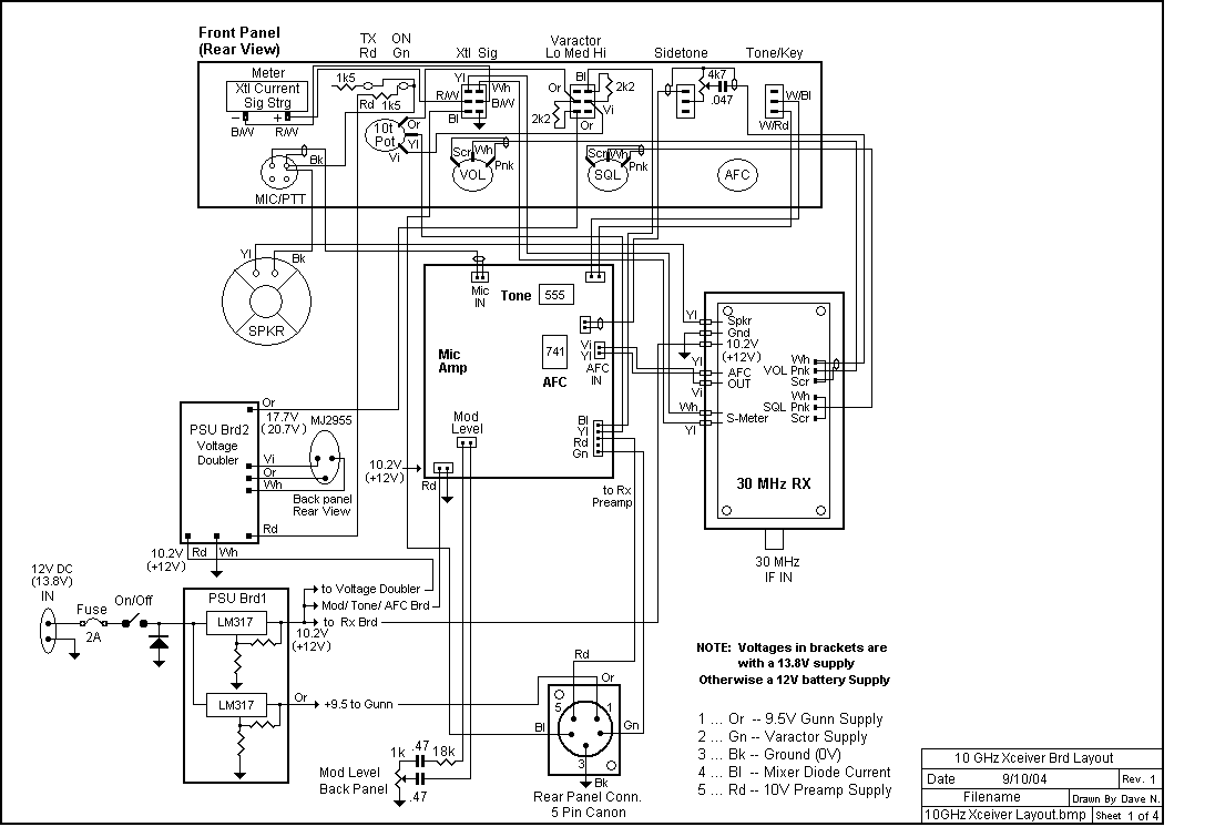
Below are wiring layout and schematics for several sections of the transceiver. The circuit for the receiver and AFC
can be found in Ham Radio Magazine 10 gig article; Aug 1978; Pg. 10 -15; by Klaus, DJ7OO.
The 30MHz pre-amp, that is mounted at the Gunnplexer head, comes from Ham Radio Magazine; Oct 1978;
Pg. 38 -41; by James, W1HR
This pic is the main layout

This pic shows the circuit for the modulator, tone generator and AFC control.

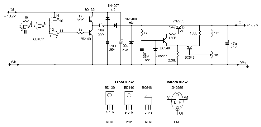
This pic shows the circuit for the voltage doubler to supply the Varactor Diode. In reality for a 12V supply you get
around 18 - 20V output.

Page Created 27 Feb. 2005 Dave Nelson


